
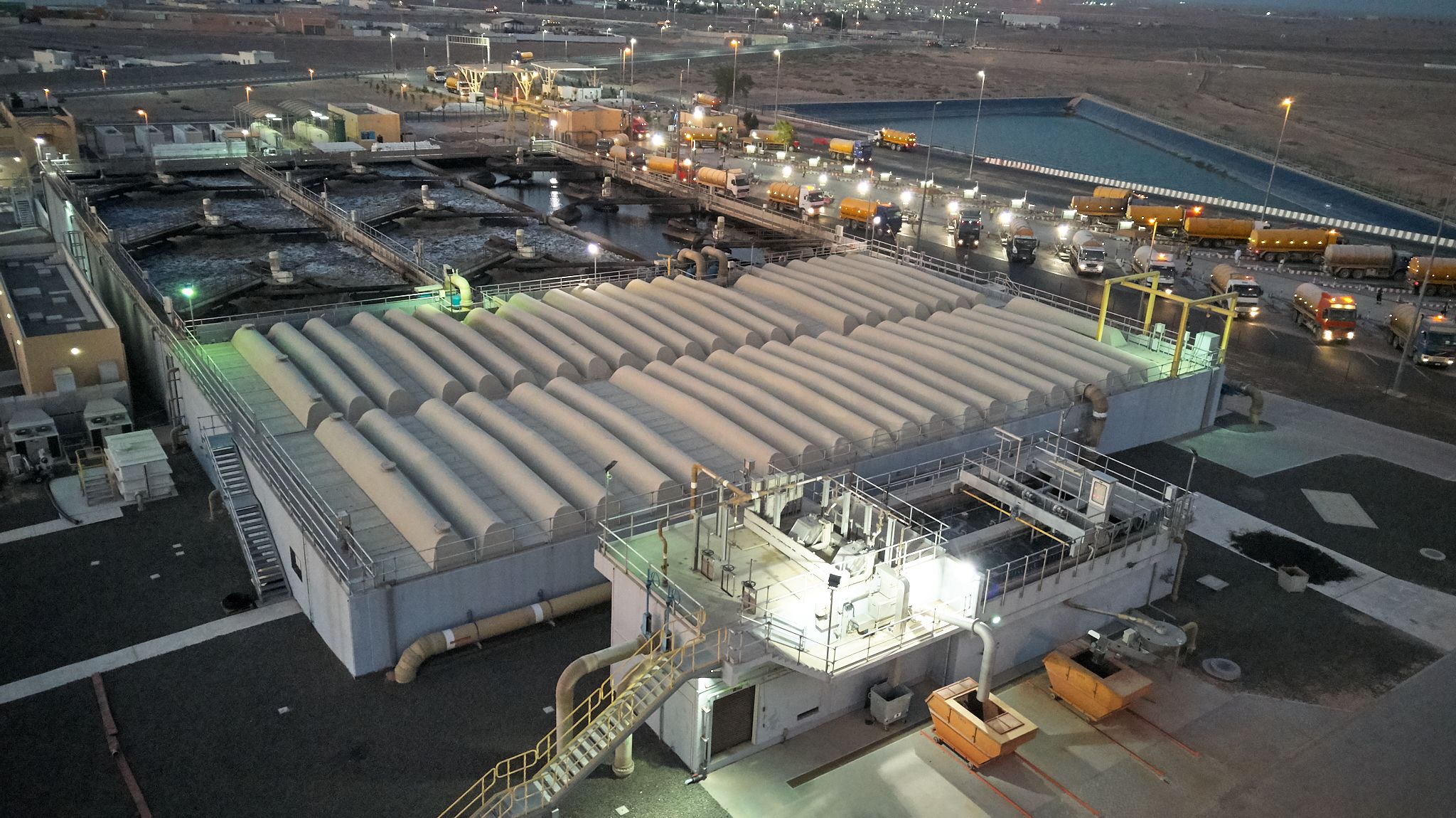
The Al Saja’a Bio Refinery is the main asset operated by Qatra. Located in the Sharjah Industrial Area of Sharjah, it daily receives up to 1,600 tankers carrying Municipal Wastewater from areas not covered by a network. This is equivalent to around 35,000 m3/day or 110,000 people equivalent. The capacity is currently being expanded to double it by mid-2022 in order to cope with the increase of tankers in the Emirate of Sharjah.
The wastewater is cleaned through a process comprising different steps bringing this water back to life with a quality suitable for irrigation and landscaping. This Treated Water can further be cleaned in order to enhance its quality and match, if not to exceed, the one produced from desalination plants but using four times less energy. Following the examples of several schemes working abroad like in the US or Australia, Qatra is currently developing different projects to produce such water with the objective to increase its use as a sustainable alternative to desalinated or aquifer water.
At the core of the Bio Refinery treatment process are the Sequential Batch Reactors. This technology is reliable and has a low power consumption per m3 in comparison with other wastewater treatment processes. The expansion under development will use an improved version of this technology with the promise to further reduce the power consumption by 30%.
You will find below an overview of this plant as well as videos and 360 degrees for a powerful immersio into this unique facility in Sharjah.
Note: Municipal Wastewater is opposed to Industrial Wastewater. It is collected from residential and commercial areas and has limited toxic components (detergents, heavy metals, chemicals…).

Each tanker is equipped with a card that needs to be tagged at the payment gate. This card is holding the customer account and allows Qatra to follow the history and compliance of discharge and compliance. The Gate comprises 2 lanes, one normal and one fast track.
In a daily average, 1,500 tankers driving from all over the Emirate of Sharjah come to discharge their load of wastewater into 20 bays. They carry municipal wastewater coming from areas not yet connected to a sewage network. Each tanker is tested to check if the wastewater quality complies with discharge standards so it doesn’t harm the biological process.
The coarse screens are the first treatment step. They remove large solids, rags, and debris from wastewater, and have openings of 15 mm. These solids must be removed at the very beginning of the water treatment process, as these solids could make the whole system less efficient, damage expensive and essential equipment or contaminate the output water.
After coarse screening, the screened sewage flows by gravity into the influent pumping station, which is equipped with three submerged pumps. These pumps transfer the sewage up to the influent distribution chamber, the highest point of the plant, where the incoming sewage flow is evenly distributed towards the two pre- treatment units.
The influent pumping station is connected to the odour treatment unit and is provided with removable covers to allow for visual inspection.
The pre-treatment consists of:
Indeed, grit and grease
are part of the sewage that comes from tankers and have to be
removed as much as possible before the subsequent biological
treatment.
The combined grit and grease removal system is a longitudinal aerated
chamber, with a grease removal compartment alongside. The
screened sewage is introduced in the grit chamber at one side of the
chamber and is discharged at the opposite side of the chamber. Air
diffusers are provided in the grit chamber only at one side. By the
driving force of the aeration, a spiral flow of the sewage in the grit
chamber is created from the inlet to the outlet. The purpose of the
aeration is to keep the organic solids in suspension and to allow only
the sand and grit to settle in the chamber. At the same time, the light
fat and grease matters rise to the surface. To remove the grease, a
separation wall with openings in the grit chamber is provided to create
a calm zone adjacent to the grit chamber.
After the grit and grease removal, the pre-treated sewage flows by gravity into the influent balancing tanks that are very important to level-out the hydraulic loads (influent flow variations) and the organic loads (variations in sewage composition). The influent balancing tanks are also needed as a buffer/storage to allow a discontinuous feeding of the subsequent biological reactors.
The Sequential Batch Reactor (SBR) is the heart of the treatment process at Al Saja’a Bio-Refinery. Through different steps, a biological process separates the clean water from the dirt.
A complete batch comprises the 4 below steps:
STEP 1. FILL, the wastewater is filled into the tank (also called a reactor, the refinery has 6 reactors.)
STEP 2. REACT, bacteria already present in the tank eat the dirt, making them to grow. Air is injected and the water is mixed to optimize bacteria growth.
STEP 3. SETTLE, no more mechanical movements, the
bacteria are too heavy and fall at the bottom. This is called sludge.
STEP 4. DRAW, the clear water at the top is pumped out from the tank to the following treatment step (disc filters), and the sludge at the bottom also removed from the tank to go to the sludge treatment process.
A batch lasts between 6 to 8 hours.
The only function of the secondary effluent buffer tank is to receive and buffer the discontinuous secondary effluent flow from the SBR Tanks, in order to direct a continuous flow by gravity towards the tertiary treatment.
This is the ultimate treatment process, chlorine is added to the water, so it kills the remaining bacteria. At this stage, the water which is called “Treated Effluent” or TE is ready to be reused for irrigation or further treatment.
Chlorine is used to destroy germs in the effluent of wastewater treatment plants. One of the reasons for the widespread use of chlorine disinfectants is that they provide a “residual” level of protection against waterborne pathogens. A chlorine residual is a low
level of chlorine remaining in water after its initial application. It is the chlorine portion available for disinfection. Many waterborne germs are either killed or rendered incapable of reproducing, helping to prevent
waterborne disease outbreaks. Free residual chlorine constitutes an important safeguard against the risk of subsequent microbial contamination after treatment —a unique and significant benefit for public health.
The water coming from the Sequential Batch Reactors is clear but still have very small suspended solids. It is passing through filters that will ensure that these solids are removed. The water flows at the bottom while it is cleaned at the top. The constant disc rotation ensures that the cleaning is done evenly and continuously.
The sludge from the Sludge Treatment still contains more than 80% of water. The drying beds are simply large area covered with sludge and where the water evaporates during several days. The sludge is regularly moved to increase the evaporation rate. Once completed,
the dryness is around 80%, so a major reduction in volume and weight. The product (dried sludge) can then be used for composting, landscaping or burnt to produce energy.
The Storage Lakes store the Treated Water produced by the Bio Refinery. They are a unique place in Sharjah where the wildlife has spread, and where can be seen different species of birds.
The sludge coming from the Sequential Batch Reactors has more than 99.5% of water that needs to be removed to reduce the weight and volume.
The sludge treatment is done in three distinct stages:
The bio refinery is full of electrical equipment that need to be powered and controlled individually. The motor control center is where the power is safely distributed to the equipment. The installed capacity of the refinery is 4 MW.
The bio refinery is full of electrical equipment that need to be powered and controlled individually. The motor control center is where the power is safely distributed to the equipment. The installed capacity of the refinery is 4 MW.
The Odour Control Unit treat the odour compounds of the wastewater, and primarily Hydrogen sulfide gas (H2S) that results from septic conditions during the collection and treatment of wastewater. This colorless gas, known for its rotten egg smell, is produced by the biological reduction of sulfates and the decomposition of organic material. It forms at virtually every point in a wastewater system. Beyond its nuisance odor, hydrogen sulfide also poses a serious problem for the structural integrity of the treatment system (corrosion caused by the sulfuric acid formed from the interaction of H2S with moisture). Of greatest concern are the safety hazards associated with H2S. Hydrogen sulfide gas is acutely toxic and a leading cause of death among workers in sewer systems. Although disagreeably pungent at first, it quickly deadens the sense of smell and a worker may not be aware that it is there. Even at low concentrations in air, exposure to hydrogen sulfide has been linked to fatigue, headaches, eye irritation, sore throats and other health problems.
In case the Influent or Treated Effluent quality doesn’t meet the contractual quality requirements, it must be stored to be retreated. It is the role of the 30,000 m3 emergency lagoon.
The plant is powered from the grid from the Sharjah Electricity and Water Authority (SEWA). The Power Substation role is to lower the voltage from SEWA and to feed each Motor Control Centre.
An on-site laboratory performs tests daily to ensure that the specifications are met with the quality of Treated Water and other By-Products like the sludge moisture content.
The Control room is the brain of the plant. Field sensors continuously send a variety of information like tank levels, pH, flow, and an automatic system called SCADA regulates back all actuators (valves, pumps, chemical dosing…). 24/7 operators monitor closely the plant performances and take actions when issue is detected.
Water level checks at Laboratory.
Explore our assets in 360 degrees and with virtual reality.


(VR videos can only play on YouTube mobile app)
This chart gives a summary of the Treated Water produced by the Refinery for 2018 and 2019. Values are daily averages for each month and labelled in cubic meters (m3/day).
(m³)
©2026 – Qatra


